|
||||||||||||
|
|
|
|||||||||||
76GHz
Link to G8BKE Website & 76GHz report 47 GHz
24 GHz10 GHz 5.7 GHz 3.4 GHz My 3.4 GHz
portable
2.3 GHz 1.3 GHz Investigations More Stuff
|
|
The G8ACE
MKII OCXO
This
OCXO left uses a 5th overtone crystal and has been developed to
provide improved frequency stability when operating on all the microwave
bands. It
has varicap frequency control for fine preset adjustment or for connection to
a PLL such as the
Reflock CT1DMK design. Click here or on
the image left for more MKII OCXO
information. |
||||||||||
|
|
||||||||||||
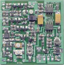
An Ovened
Reference Oscillator
This module pictured to the right uses the same oven circuit as
the MKII OCXO but is for use at 5 or 10 MHz or any specific similar
frequency. Using a fundamental mode
AT cut crystal the circuit incorporates crystal drive level control and
provides a 0dbm sinusoidal output signal
into 50 ohms. The circuit was designed by G8CPJ and implemented here using
mainly surface mount components and integrated into the existing G8ACE oven
design. The Oscillator is varicap controlled for phase locking to GPS, BBC Radio 4 on 198Khz or similar reference transmissions. The 10 MHz signal can be distributed around your microwave station via an amplifier to phase lock OCXOs as above. This is a new version of the pcb and is now now 40mm square to ease construction. Box Size 55 x 55mm. more information. |
|
|||||||||||
|
|
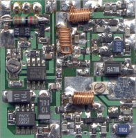
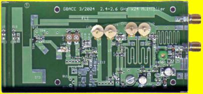
A x24 multiplier for use with the MKII OCXO either as part of a multiplier chain or test signal source Using
four semiconductors the output power of the module shown left is 40mw from
less than 1mW drive at the band centre.
Drive level control is incorporated.
All tuned inductors are printed.
The Output Filter is located at the top of the PCB. The on board 9v regulator on the
underside. Omitting the last stage
the module can be used at 23cms. Module size is 110 x 55 x
30mm. Further details here
or click the image. |
|||||||||||


Page last updated 19/02/2006