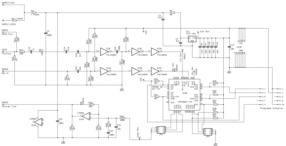
Phase
Locked Loop – Using the Luis Cupido CT1DMK CPLD Design
The most basic circuit
supported by this printed circuit board uses the component outlines
shown in black . The omitted component positions are
coloured yellow. Using the PLL for the
higher microwave bands
effects such as crosstalk back into the OCXO were noted and therefore a
mmic to provide additional
reverse isolation can be included as required.
Various other options can be
included for additional RF
output and for monitoring the control loop voltage to the OCXO vari-caps.
CPLD programming using the
standard CT1DMK .pof files is via the central connector. Choice of
configuration and comparator
type is via handbag links at the bottom RH corner of the PCB.
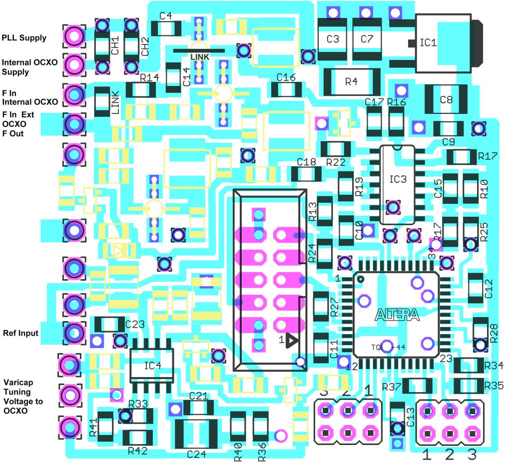
This printed circuit fits a
55 x 55 x 40mm deep box where the OCXO is fitted in the
opposite end of the box with
certain constraints. Otherwise a 20mm
deep box maybe used.
Printed Circuit Component Positions
Circuit for the
basic version.